Arduino Programming
- Nov 23, 2022
- 4 min read
Updated: Nov 30, 2022
There are 4 tasks that will be explained in this page:
Input devices:
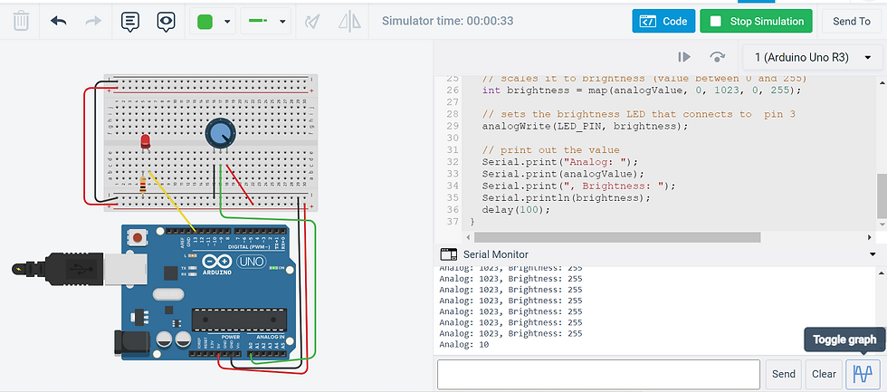
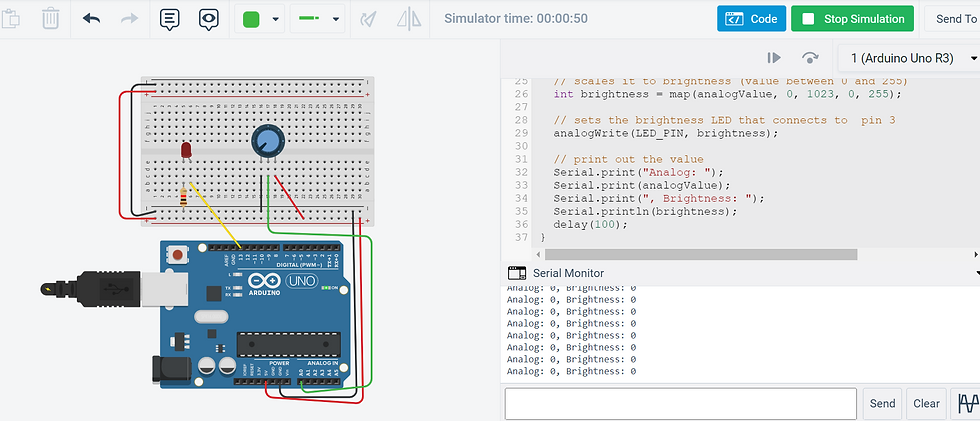
Interface a potentiometer analog input to maker UNO board and measure/show its signal in serial monitor Arduino IDE.
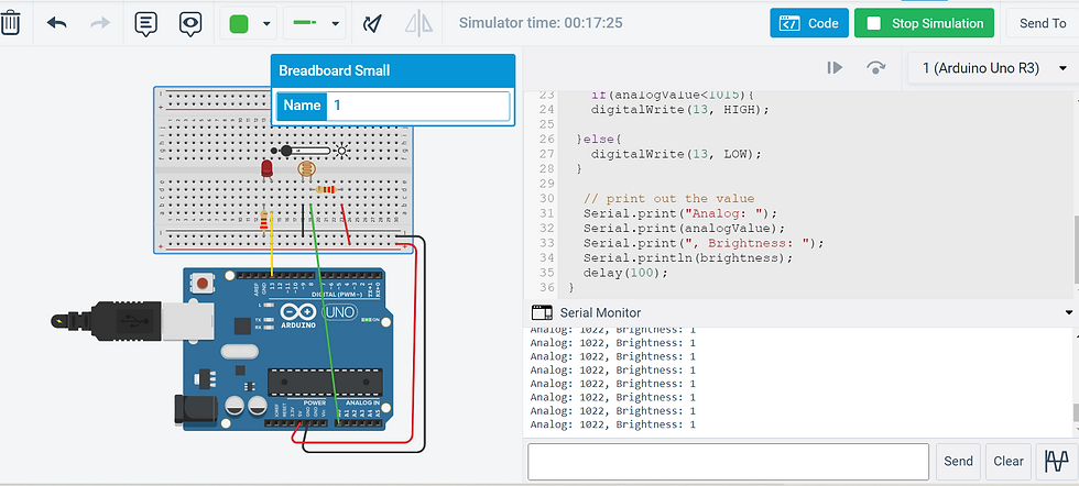
Interface a LDR to maker UNO board and measure/show its signal in serial monitor Arduino IDE
Output devices:
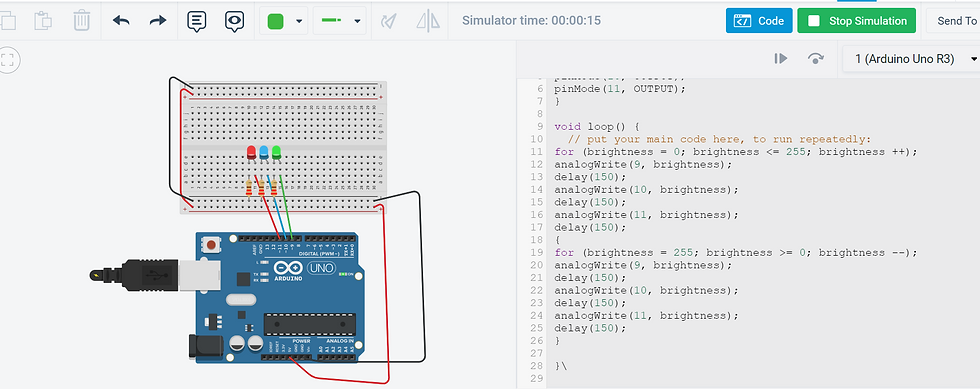
Interface 3 LEDs (Red, Yellow, Green) to maker UNO board and program it to perform something (fade or flash etc)
Include the pushbutton on the MakerUno board to start/stop part 2.a. above
For each of the tasks, I will describe:
The program/code that I have used and explanation of the code.
The sources/references that I used to write the code/program.
The problems I encountered and how I fixed them.
The evidence that the code/program worked in the form of video of the executed program/code.
INPUT DEVICES: POTENTIOMETER
CODE & EXPLANATION
Code | Explanation |
int LED_PIN = 13; // the PWM pin the LED is attached to // the setup routine runs once when you press reset: void setup() { // initialize serial communication at 9600 bits per second: Serial.begin(9600); // declare LED pin to be an output: pinMode(LED_PIN, OUTPUT); } // the loop routine runs over and over again forever: void loop() { // reads the input on analog pin A0 (value between 0 and 1023) int analogValue = analogRead(A0); // scales it to brightness (value between 0 and 255) int brightness = map(analogValue, 0, 1023, 0, 255); // sets the brightness LED that connects to pin 3 analogWrite(LED_PIN, brightness); // print out the value Serial.print("Analog: "); Serial.print(analogValue); Serial.print(", Brightness: "); Serial.println(brightness); delay(100); } | I am setting pin 13 as the connection to the LED. Serial.begin(9600) indicates I am establishing a connection between the computer and the arduino board I am declaring LED pin to be the output Reads the input value from analog pin A0, which is between 0 and 1023 Scaling the brightness values of 0-255 with analogValue. I am setting the brightness of the LED that connects to pin 13 This will allow the values of analogValue and brightness, with a delta of 100 milliseconds between each value.
|
SOURCES & REFERNCES
PROBLEMS ENCOUNTERED & HOW I FIXED THEM Previous codes that did not accomplish the challenge consisted of the led turning on and its brightness not being affected by the turning of the potentiometer, and the led not turning on no matter how much i turn the potentiometer. The problem was I did not include a program line that scaled brightness to the analog value. After adding it in, the code worked.
VIDEO EVIDENCE
INPUT DEVICES: LDR
CODE & EXPLANATION
Code | Explanation |
int LED_PIN = 13; // the PWM pin the LED is attached to int light; // the setup routine runs once when you press reset: void setup() { // initialize serial communication at 9600 bits per second: Serial.begin(9600); // declare LED pin to be an output: pinMode(LED_PIN, OUTPUT); } // the loop routine runs over and over again forever: void loop() { // reads the input on analog pin A0 (value between 0 and 1023) int analogValue = analogRead(A0); // scales it to brightness (value between 0 and 255) int brightness = map(analogValue, 0, 1023, 255, 0); // sets the brightness LED that connects to pin 3 analogWrite(LED_PIN, analogValue); if(analogValue<850){ digitalWrite(13, HIGH); }else{ digitalWrite(13, LOW); } // print out the value Serial.print("Analog: "); Serial.print(analogValue); Serial.print(", Brightness: "); Serial.println(brightness); delay(100); } | I am setting pin 13 as the connection to the LED. Serial.begin(9600) indicates I am establishing a connection between the computer and the arduino board I am declaring LED pin to be the output Reads the input value from analog pin A0, which is between 0 and 1023 Scaling the brightness values of 0-255 with analogValue. I am setting the brightness of the LED that connects to pin 13 I am setting that if analogValue is less than 850, the LED will turn on. (Lower resistance from LDR, more light in the LED) Else (analogValue>850), the LED will turn off. This will allow the values of analogValue and brightness, with a delta of 100 milliseconds between each value. |
SOURCES & REFERNCES
PROBLEMS ENCOUNTERED & HOW I FIXED THEM
The main problem I faced was that the values of analog and brightness were scaled wrongly at first. It is supposed to be that when analog increases, brightness decreases as analog is the resistance of the LDR. However, when I tried to fix it by switching the numbers around in the scaling of brightness code, the relationship between analog and brightness was still wrong with analog decreasing and brightness decreasing. Turns out the pins were placed at incorrect positions, as well as the negative and positive connection being switched from the LDR pins. From this I learnt that even though the board is working and the LED is lighting up, the connections may still be wrong.
VIDEO EVIDENCE
OUTPUT DEVICES: 3 LEDs
CODE & EXPLANATION
Code | Explanation |
int brightness = 0; void setup() { // put your setup code here, to run once: pinMode(9, OUTPUT); pinMode(10, OUTPUT); pinMode(11, OUTPUT); } void loop() {
for (brightness = 0; brightness <= 255; brightness +=1); analogWrite(9, brightness); delay(150); analogWrite(10, brightness); delay(150); analogWrite(11, brightness); delay(150); { for (brightness = 255; brightness >= 0; brightness -=1); analogWrite(9, brightness); delay(150); analogWrite(10, brightness); delay(150); analogWrite(11, brightness); delay(150); } } | I am creating an integer variable called brightness, and of starting value, 0 I am setting pin 9,10 and 11 as outputs for each LED of 3 LEDs. This code sets brightness = 0, and if brightness is less or equals to 255, it will increment 1 by itself. This will take effect on pin 9,10 and 11. The delay of 150 milliseconds will take place between each +1 increment This code sets brightness = 255, and if brightness is more or equal to 0, it will go down by 1 by itself. This will take effect on pin 9,10 and 11. The delay of 150 milliseconds will take place between each increment of -1. |
SOURCES & REFERENCES
PROBLEMS ENCOUNTERED & HOW I FIXED THEM
The main problem I encountered was not with the code, but with my setup. I often had the positve and negative pins of each led in the wrong position, as well as the jumper cables connecting to the wrong places. This was due to using so many wires and being confused. Fixing this was simple as I just had to attach each wire correclty before adding a new wire.
VIDEO EVIDENCE
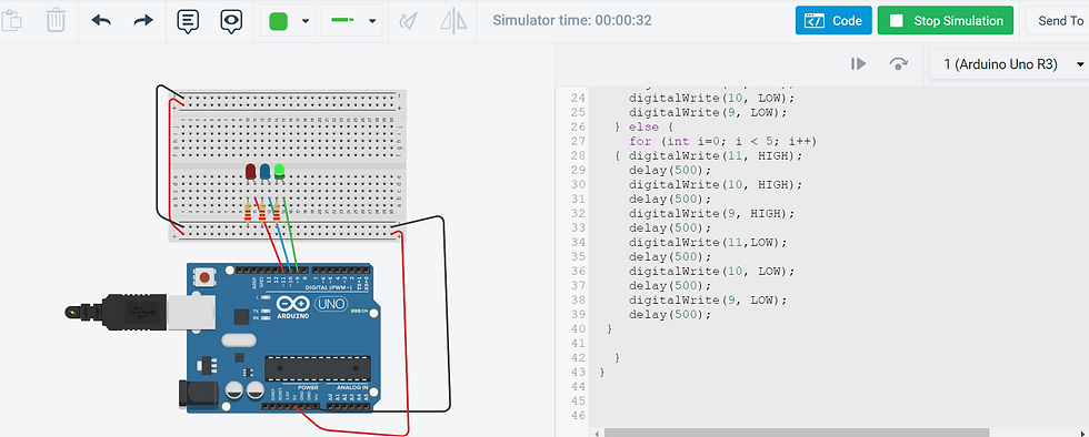
OUTPUT DEVICES: PUSHBUTTON FOR 3 LEDs
CODE & EXPLANATION
Code | Explanation |
void setup() {
// put your setup code here, to run once:
//start serial connection
Serial.begin(9600);
//configure pin 2 as an input and enable the internal pull-up resistor
pinMode(2, INPUT_PULLUP);
pinMode(11, OUTPUT);
pinMode(10,OUTPUT);
pinMode(9, OUTPUT);
}
void loop() {
// put your main code here, to run repeatedly:
//read the pushbutton value into a variable
int sensorVal = digitalRead(2);
//print out the value of the pushbutton
Serial.println(sensorVal);
// Keep in mind the pull-up means the pushbutton's logic is inverted. It goes
// HIGH when it's open, and LOW when it's pressed. Turn on pin 13 when the
// button's pressed, and off when it's not:
if (sensorVal == HIGH) {
digitalWrite(11, LOW);
digitalWrite(10, LOW);
digitalWrite(9, LOW);
} else {
for (int i=0; i < 5; i++)
{ digitalWrite(11, HIGH);
delay(500);
digitalWrite(10, HIGH);
delay(500);
digitalWrite(9, HIGH);
delay(500);
digitalWrite(11,LOW);
delay(500);
digitalWrite(10, LOW);
delay(500);
digitalWrite(9, LOW);
delay(500);
}
}
}
| Serial.begin(9600) indicates I am establishing a connection between the computer and the arduino board
we declare that PIN 2 is an INPUT and enable the internal pull up resistor. So, by default, PIN2 status will always be HIGH We declare that pin 11,10 and 9 are outputs
We declare that the serial monitor reads the input of PIN2 and writes into an INTEGER variable, sensorVal. Serial monitor displays the value of sensorVal if it is pressed.
If the button is not pressed, pin 9,10 and 11 will be turned off
If the button is pressed, the following action will repeat 5 times: Pin 11,9 and 10 will turn on and off with 500 millisecond pauses between each blink for 5 blinks. |
SOURCES & REFERENCES
This code is taken and modified from my code for the pre-practical, for the button. Which was also downloaded and modified from the learning package for Arduino.
PROBLEMS ENCOUNTERED & HOW I FIXED THEM
The main issue I had was just the connections once again, and trying to choose the best delay for the flashing of the LEDs. I was hoping to find a way to make the flashing more smooth and connected to each other, but I did not figure it out. For the connections, I just redid them and worked the jumper wires slowly from each pin.
VIDEO EVIDENCE
PRACTICAL
Code that we used to flap the wings and light up the LED:
CODE |
#include <Servo.h> Servo myservo; // create servo object to control a servo // twelve servo objects can be created on most boards int pos = 0; // variable to store the servo position void setup() { myservo.attach(9); // attaches the servo on pin 9 to the servo object pinMode(10, OUTPUT); } void loop() { for (pos = 0; pos <= 165; pos += 1) { // goes from 0 degrees to 165 degrees myservo.write(pos); // tell servo to go to position in variable 'pos' delay(9); // waits 9ms for the servo to reach the position } for (pos = 165; pos >= 0; pos -= 1) { // goes from 165 degrees to 0 degrees myservo.write(pos); // tell servo to go to position in variable 'pos' delay(9); // waits 9ms for the servo to reach the position } } |
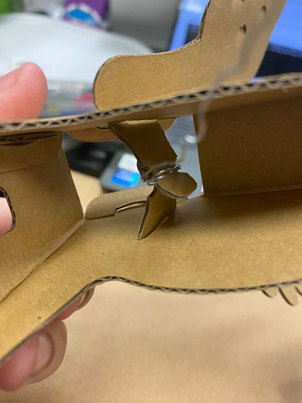
To connect the wings of the pegasus/pony, we just used the metal wire instead of the rubberband as it was more durable. We wrapped it around the connections of the wings, and attached the wire to the servo. We did trial and error with the angle of the servo to get the perfect flap, as well as trial and error with the delay to get a majestic flap of the wings.
Metal wire connection
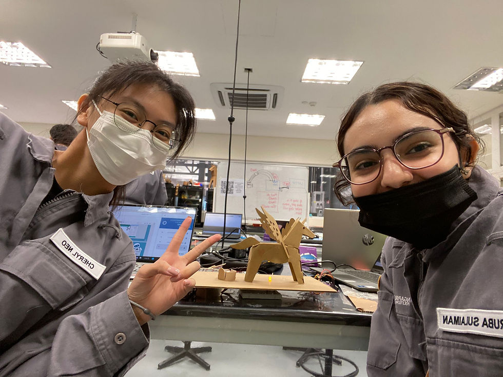
As our extra component, we added a yellow LED light that acts as warm lighting for our pegasus/pony. For aesthetics, we added a flag and a cutiemark :)
To make the whole setup more compact, we cut a hole where the servo would slip in, and added a fence around the servo using icecream sticks.
We also thought of leaving the pegasus/pony unattached to the board, to make it a walking pony, but this compromised the flapping of the wings. So we just attached it to the board :(.
Even though we struggled with the code for the led, where only 1 out of 2 LED would light up, it was the most fun practical by far.
Hero shot


REFLECTION
This topic was definitely the most challening one yet and took a significant amount of time for me to grasp the concept of this kind of coding. Nonetheless, I did enjoy arduino coding immensely and the satisfaction from getting a code right and working on my own somewhat was great. TinkerCAD helped greatly in setting up the arduino board and checking if the code works when I couldn't get my hands on the arduino board, as well as helping me check whether the code works with the setup before I build the setup myself as it saves me time and is faster on TinkerCAD.
For the practical, it was enjoyable and quite stressful as we had a time limit and were very independent in creating our own codes. It was overall a frutiful practical.
Arduino has taught me greatly about coding, and that different codes can work to accomplish the same action.


Comments